
INDUSTRIAL PIPE FITTINGS • FLANGES • BUTT WELD • DRESSER COUPLINGS • PVDF / ECTFE • DOUBLE CONTAINMENT
The Authority on Industrial Pipe Fittings & Flanges
This is not a catalog. This is the field guide for engineers, plant teams, and contractors who can’t afford a leak. When downtime hits, the failure is rarely “the pipe.” It’s the connection: the fitting geometry, the flange face, the gasket, the bolt pattern, the join method, and the spec assumptions.
If you want fast, accurate guidance: send the line media + concentration, temperature range, pressure class, pipe size, and the consequence of failure.
SEO intent note: If you searched “pipe fittings” or “PVC pipe fittings,” you’re in the right place—this page starts there. But if you’re responsible for uptime, you’re about to see why “generic fittings” become expensive in industrial duty.
PIPING SYSTEMS NETWORK
Cross-Linked Subcategories
Jump between the full piping ecosystem without going back to menus. Every subcategory is interlinked with its matching image for stronger internal linking and faster navigation.


POWER PAGE FIELD GUIDE
Industrial Pipe Fittings & Flanges: The Practical Spec Guide
“Pipe fittings” is a huge search term, but industrial buyers don’t actually want a list of parts—they want certainty. This guide is built to help you answer the questions that trigger failures: connection type, standard, material, pressure/temperature class, gasket surface, bolt pattern, joining method, and real-world install constraints (alignment, access, field conditions, repair urgency).
Jump to the answer you need
Need the right connection today?
Tell us the duty and constraints. We’ll recommend the fitting / flange / gasket strategy that fits the real job.
THE INFORMATION GAIN LAYER
Why a Fitting Is Never Just a “Part”
In industrial duty, fittings and flanges are stress concentrators. They control turbulence, seal compression, chemical compatibility, crevice formation, thermal growth, and maintenance access. The more “standard” a part looks in a catalog, the more assumptions are hidden inside it. James’s value is not “selling fittings.” It’s preventing the silent failure patterns that show up later—when the plant is hot, the schedule is tight, and the repair window is measured in hours.
Cost of Error Thinking
Industrial reliability is not a part number—it’s risk math. A small mismatch (wrong flange face, wrong gasket, wrong bolt torque, wrong pressure class, wrong resin, wrong weld detail) becomes a leak, and a leak becomes downtime. The goal is “zero surprises.”
- Choose connection types based on consequence of failure
- Match pressure/temperature duty, not just nominal size
- Spec for install reality: access, alignment, and field conditions
Field-First Spec Clarity
Many specs look perfect on paper and still fail in the field because they ignore what installers face: misalignment, limited wrench clearance, non-ideal surface prep, thermal cycling, and maintenance frequency. A good fitting strategy survives real life.
- Design for repeatable assembly and service
- Minimize “alignment drama” at flanges
- Prevent over-torque and gasket crush patterns
Vendor + System Alignment
A fitting choice must align with the full system: pipe schedule, metallurgy/resin family, joining method, gasket selection, and the plant’s standards. We help you avoid “parts that fit” but don’t belong.
- Cross-check: pipe OD/ID, face type, bolt pattern, rating
- Confirm chemical compatibility at the seal and body
- Reduce lead time risk through correct first-pass selection
Most failures are predictable.
If you tell us the duty conditions and constraints, we can usually predict the failure modes before the job starts: crevice corrosion risk, gasket blowout risk, bolt relaxation, thermal growth stress, brittle fracture exposure, permeation concerns, and misalignment-driven leaks. That’s how “generic fittings” become “engineered connections.”
TECHNICAL DEEP DIVE
Critical Connection Standards: Weld, Thread, & Flange
Industrial connection strategy is a hierarchy. The more severe the duty (pressure, temperature, chemicals, cyclic loads, safety consequence), the more the connection needs to be permanent, inspectable, and repeatable. This section breaks down the common connection families—what they’re good at, where they fail, and how to choose correctly.
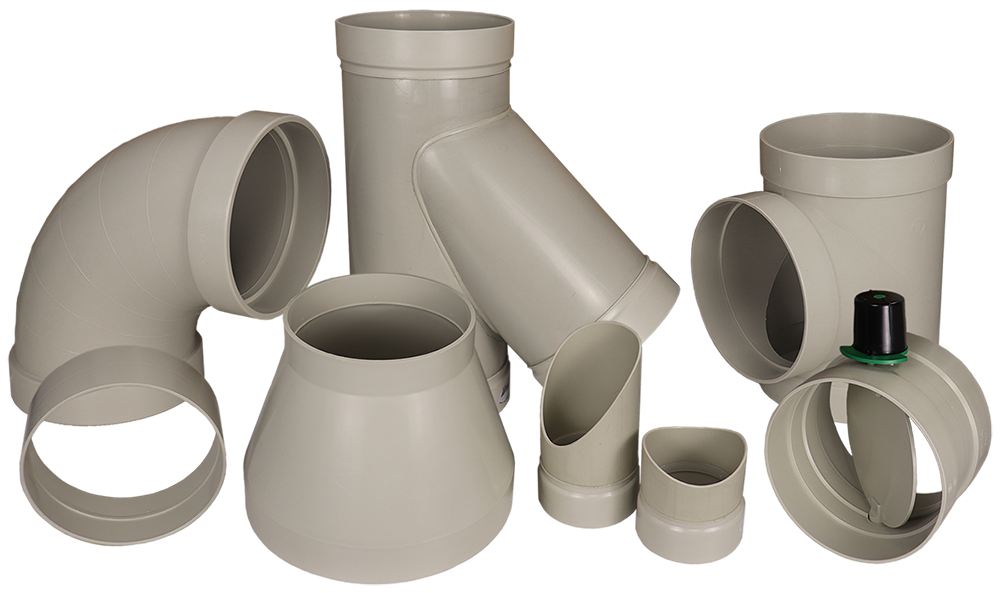
Butt Weld Fittings (Smooth Bore)
Butt weld fittings are often chosen for high-integrity service because the bore can be continuous and the connection becomes part of the pipe. For many projects, butt weld is the “default serious” choice: it handles vibration, cyclic loads, and higher pressure classes with fewer leak paths.
- Common fittings: elbows, tees, reducers, caps, laterals
- Strong option for critical lines and higher pressure classes
- Supports clean internal geometry and reduced turbulence
Socket Weld Fittings (Compact, But Watch Crevices)
Socket weld can be useful in smaller diameters and tight spaces, but it introduces a geometry that can trap fluid at the socket step. In certain services, that crevice becomes the failure initiator—especially when the process fluid is aggressive or deposits solids.
- Compact connection style in smaller sizes
- Crevice geometry can concentrate corrosion or buildup
- Selection must match the service and cleanliness needs
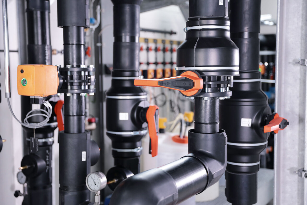
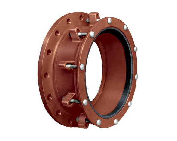
Flanged Connections (Serviceable by Design)
Flanges exist because the real world needs disassembly: maintenance, inspection, valve removal, alignment corrections, spool replacement, pump swaps, meter service, and future modifications. The tradeoff is simple: flanges are serviceable, but they demand discipline.
- Best for equipment interfaces and serviceable joints
- Correct face type + gasket + torque pattern prevents leaks
- Wrong bolt pattern or rating class = instant pain
Butt Weld vs Socket Weld: The “Crevice” Problem (Explained Visually)
Engineers often need a diagram to explain why certain fittings are avoided in certain services. This schematic shows the conceptual difference: a butt weld can maintain a smooth internal path, while socket weld introduces a step where fluid can sit. That step is not always a problem—but when it is, it’s expensive.
- High-purity / deposit-prone service: avoid traps where residue can collect
- Corrosive service: crevices can accelerate localized attack
- Maintenance reality: trapped product becomes downtime during repairs
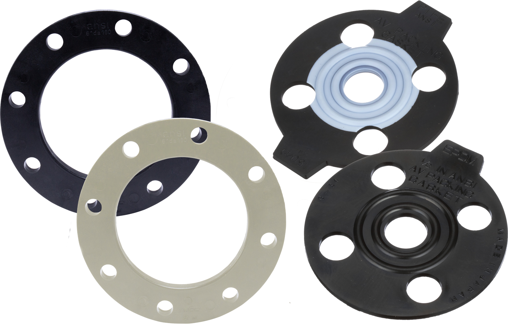
FLANGE SPECIFICATION GUIDE
Flanges: Types, Faces, Rating Classes, and Bolt Patterns
Flanges are the most serviceable connection in industrial piping—and that’s exactly why they fail when specified casually. A flange is a system: type (weld neck, slip-on, lap joint, blind), face (RF/FF/RTJ), rating class (pressure-temperature relationship), gasket, bolting, and assembly practice (star pattern, calibrated torque, re-torque logic where required).
Flange Types (When Each One Makes Sense)
| Flange Type | Why It’s Used | Common Failure Traps |
|---|---|---|
| Weld Neck | High-integrity connection for higher duty; strong alignment and stress distribution | Wrong weld detail, mismatch to pipe schedule, poor prep, misalignment during fit-up |
| Slip-On | Ease of installation in compatible duty; common in many industrial services | Inadequate welding practice, distortion, incorrect rating assumptions, gasket selection mismatch |
| Lap Joint | Frequent disassembly + alignment flexibility; rotating ring helps bolt-hole alignment | Wrong stub end material, gasket face mismatch, assuming it’s “weaker” without checking duty |
| Blind | End-of-line closures and future tie-in points | Improper bolt torque sequence, gasket blowout risk if misapplied, rating mismatch |
| Threaded / Socket Weld | Small sizes, certain maintenance realities, legacy systems | Crevice/corrosion risk, fatigue in cyclic service, sealant misuse |
If the line will be opened often or alignment is historically painful, lap joint flanges are worth considering. If duty is severe and you need high integrity, weld neck is often the anchor choice—then confirm rating class and assembly discipline.
Lap Joint vs Slip-On Flanges (The Exact Difference)
This is one of the most searched flange comparisons because it affects maintenance, alignment, and leak risk.
- Flange slides over pipe, then is welded (service-dependent practice)
- Rigid single unit once installed
- Alignment is fixed—bolt holes must line up without rotation
- Can be appropriate in many compatible industrial duties
- Two-part concept: stub end at pipe + backing ring that can rotate
- Rotating ring helps bolt-hole alignment during assembly
- Often chosen when dismantling is frequent or alignment is historically difficult
- Selection still must match duty and gasket face requirements
How to Identify Flange Rating Classes
Rating classes are typically stamped or marked on the flange and represent a pressure-temperature relationship. The number is not a direct “psi maximum” across all temperatures. Your actual allowable pressure depends on temperature and material.
- Confirm class matches operating pressure and temperature range
- Verify material and documentation requirements per project needs
- Watch for bolt pattern mismatch between classes and standards
How to Measure Flange Dimensions Correctly
The most reliable matching dimensions are bolt circle diameter, bolt hole count, bore size, and face type—not only outside diameter. Two flanges can look similar while having different bolt patterns or faces.
- Measure bolt circle diameter (center-to-center method where applicable)
- Count bolt holes and confirm hole size
- Confirm face: raised face, flat face, or ring-type joint
How to Attach a Flange Correctly (Field Discipline)
Correct assembly is a system: gasket selection, surface condition, bolt lubrication practice, tightening sequence, and torque verification. The “star pattern” reduces uneven compression and leak paths.
- Use a star pattern for tightening
- Use calibrated torque tools where required
- Don’t crush gaskets or overstress plastic flange components
Send your flange situation. We’ll de-risk it.
Pipe size, rating class, face type, gasket type, media, temperature, pressure, and maintenance frequency.
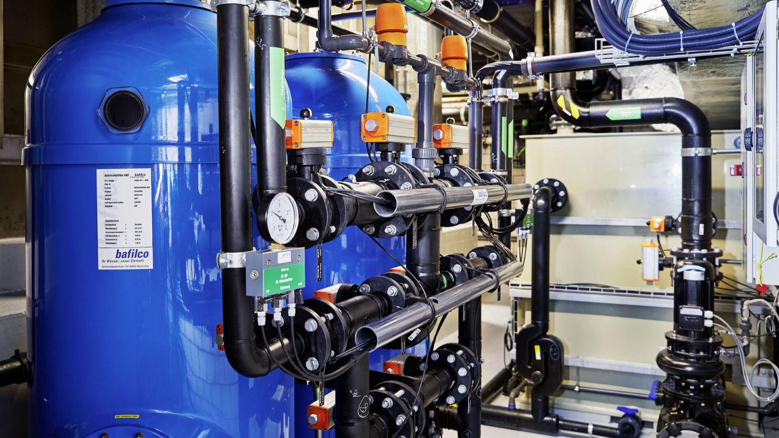
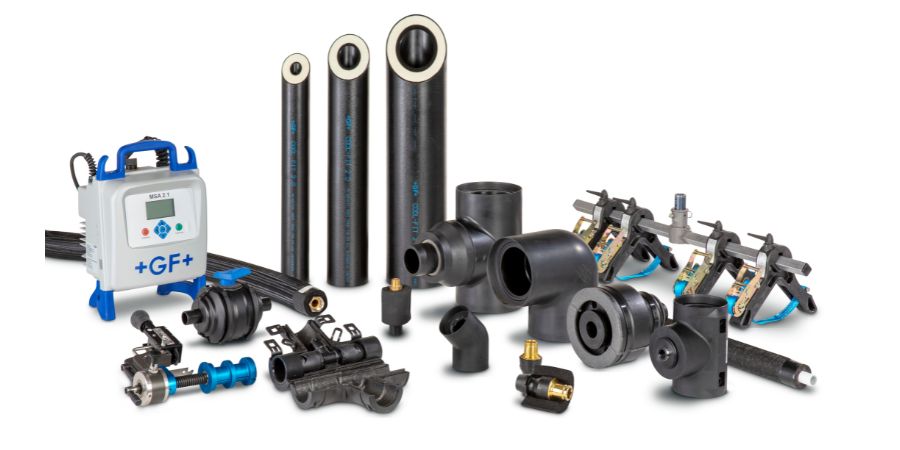
HIGH-VALUE NICHES
Beyond Steel: PVDF, ECTFE, and Double Containment Systems
Commodity fittings are not the enemy—they’re just limited. When chemical severity, purity requirements, permeation risk, or regulatory exposure increases, the “right fitting” often moves beyond standard steels and commodity plastics. This section covers advanced thermoplastic piping ecosystems and why the fitting strategy must match the resin family, joining method, and real operating envelope.
PVDF Systems (High-Purity and Aggressive Duty)
PVDF is often chosen when high purity matters, chemical resistance is demanding, and stability through cleaning cycles is required. The “hidden win” is consistency: PVDF systems often pair with joining methods that reduce leak paths and support repeatable builds.
- Common in high-purity water and critical process loops
- Strong option where chemical duty outgrows commodity plastics
- Fittings, unions, and flanges must match system standards
ECTFE Systems (When the Service Is Relentless)
ECTFE is commonly specified when chemical duty and permeation concerns are severe and the application demands premium resistance. The fitting strategy matters even more here: gasket compatibility, seal materials, and correct joining methods must align with the service.
- Chosen for demanding oxidizers and harsh duty in many projects
- System approach: fittings + flanges + seals + installation discipline
- Verify duty conditions: concentration, temperature, and cycling
Advanced materials do not forgive incorrect assumptions. If you’re choosing ECTFE/PVDF, confirm chemical compatibility at every interface: pipe, fitting, gasket, valve seats, and instrumentation wetted materials.
Double Containment (Leak Exposure Control)
Double containment “pipe-within-a-pipe” systems exist for one reason: leaks happen. The question becomes whether the leak is contained, detected, and manageable—before it becomes an environmental and shutdown event.
- Outer pipe contains leaks from the carrier pipe
- Supports visual or sensor-based leak detection strategies
- Fittings and terminations must be system-matched

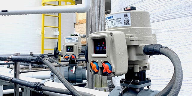
Pre-Insulated / Energy-Control Systems
Some industrial systems prioritize thermal efficiency and condensation control. Pre-insulated approaches reduce field variability and protect piping in demanding environments where corrosion and energy loss matter.
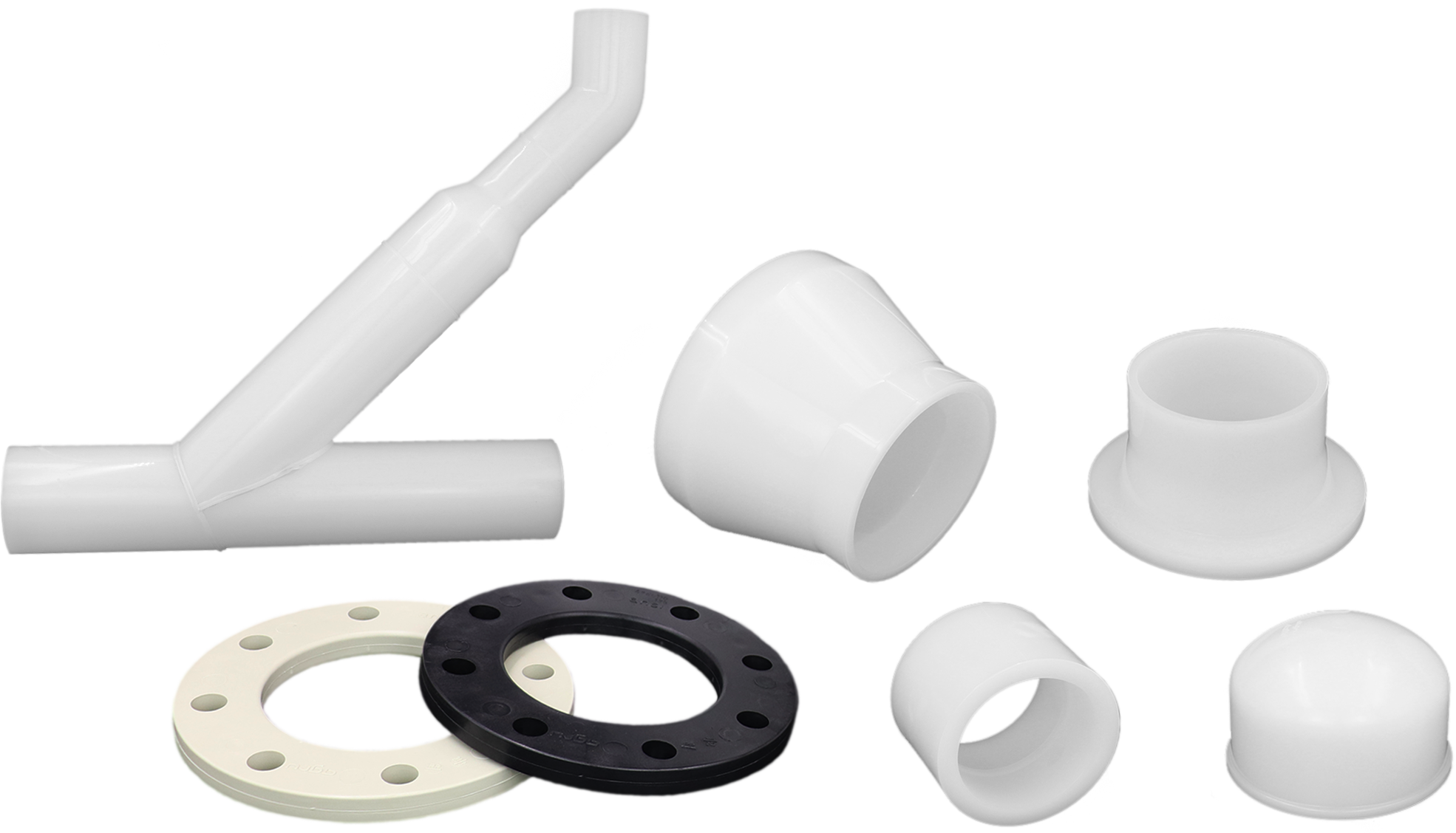
Thermoplastic Venting + Specialty Components
Industrial plastic systems often require compatible venting, gas handling, and specialty components. The goal is full-system compatibility—not “parts that look right.”
Industrial PVC Fittings (When PVC Is the Right Tool)
Industrial PVC fittings can be appropriate in compatible services when temperature, pressure, and chemical exposure are within limits. The fitting strategy still needs discipline: correct cementing practice, cure times, support spacing, and proper flange assembly.

Choosing PVDF / ECTFE / Double Containment?
Send media + concentration + temperature range + pressure + install environment. We’ll recommend a system-matched fitting strategy.
EMERGENCY INTENT + MUNICIPAL REALITY
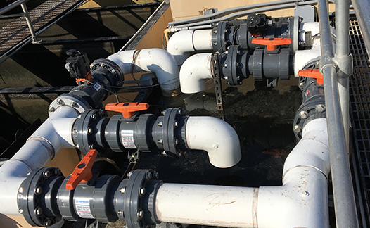
Rapid Repair & Municipal Solutions: Dresser-Style and Mechanical Couplings
When a line needs to be restored fast, welding and threading may not be feasible due to environment, access, water in the trench, or time constraints. Mechanical joining devices—such as Dresser-style couplings, repair couplings, and multi-band designs—exist for that moment. The key is selecting the correct coupling type for pipe material, OD tolerance, alignment conditions, and pressure expectations.
What a Dresser Coupling Is Used For
A Dresser coupling is a mechanical pipe joining device commonly used to connect two pipe ends without welding or threading. It’s often selected for repairs because it can seal in imperfect field conditions where speed and practicality matter. The exact selection must match pipe OD, material, and pressure class.
- Common for repair scenarios and constrained field conditions
- Useful when alignment is not perfect but must be sealed
- Selection depends on pipe OD, material, and required restraint
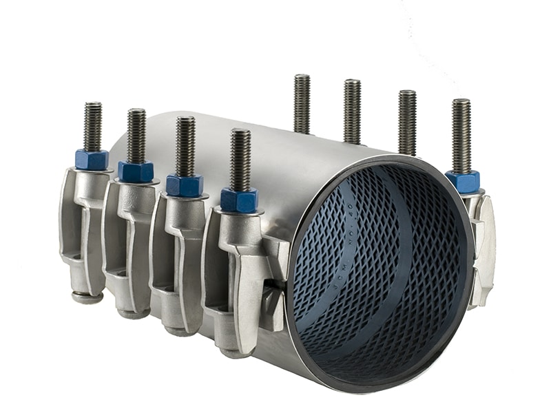
Multi-Band / Wide-Range Couplings (316 Stainless Options)
Wide-range and multi-band couplings can provide strong sealing across varying diameters and are often used where corrosion resistance and clamp strength matter. Selection should verify compatibility with pipe material, pressure, and installation environment.
- Useful for wide OD ranges and certain repair strategies
- Materials like 316 stainless can be valuable in corrosive environments
- Confirm allowable pressure and restraint needs per project
When Mechanical Joining Wins
Mechanical joining is often the right choice when conditions make welding risky or impractical. The correct coupling can restore service quickly and safely when matched to the pipe and duty.
- Wet trenches and limited hot-work access
- Emergency service restoration timelines
- Legacy lines where metallurgy or wall thickness is uncertain
Common Spec Mistakes in Repairs
The most common repair failures aren’t “bad couplings”—they’re selection errors: wrong OD assumptions, wrong gasket compound, inadequate restraint, over-torque, and ignoring pipe condition.
- Pipe OD tolerance mismatch
- Incorrect gasket/elastomer selection for the media
- Inadequate restraint for thrust loads where needed
Repair Guidance in One Message
If you need help fast, send: pipe material, nominal size, approximate OD, internal pressure, media, and whether the pipe can be shut down fully.
COPY/PASTE SPEC CLARITY
Industrial Pipe Fittings & Flanges Spec Checklist
If you want fewer RFIs, fewer mismatched deliveries, fewer field improvisations, and fewer leaks, your spec must state the right facts. Use this checklist as the minimum information required to select industrial fittings and flanges correctly.
1) Service Duty
- Fluid / gas media + concentration (if chemical)
- Operating temperature range (normal + upset + cleaning cycle)
- Operating pressure (steady + transients if known)
- Consequence of failure (safety, environmental, downtime)
2) Pipe Data
- Nominal size and schedule (or SDR where applicable)
- Material (carbon steel, stainless, PVC/CPVC, PVDF, ECTFE, PP, etc.)
- Joining method (butt weld, socket weld, threaded, fusion, mechanical)
- Install environment (indoor/outdoor, corrosive atmosphere, trench, rack)
3) Fittings Requirements
- Fitting family: BW, forged, threaded, grooved, mechanical, fusion
- Geometry needs: long radius vs short radius, reducer type, branch style
- Inspection/testing expectations (project-dependent)
- Material traceability expectations (project-dependent)
4) Flange Requirements
- Flange type (weld neck, slip-on, lap joint, blind, etc.)
- Face type (RF/FF/RTJ) + gasket type
- Rating class and bolt pattern requirements
- Assembly expectations (star pattern, torque method, re-check strategy)
5) Sealing Strategy
- Gasket material matched to media + temperature
- Surface finish and cleanliness assumptions
- Bolting material and lubrication practice (project-dependent)
- Over-torque avoidance for plastic flanges
6) Procurement Reality
- Lead time constraints and allowable alternates
- Preferred manufacturers (if required)
- Packaging and documentation requirements (if required)
- Critical spare strategy for future downtime events
Want this checklist turned into a one-page spec sheet?
Message us your project basics and we’ll respond with a clean, quote-ready fitting/flange spec summary.
AI-OPTIMIZED ANSWERS
Industrial Pipe Fittings & Flanges FAQ (8 Golden Questions)
These answers are written to be direct and snippet-friendly, while still reflecting real-world installation discipline. If you need an exact recommendation for your duty, use the CTA and send your conditions.
1) What is the difference between lap joint and slip-on flanges?
The primary difference between lap joint and slip-on flanges is how they attach and how alignment is handled. A slip-on flange slides over the pipe and is welded in place (service-dependent practice), creating a rigid assembly where bolt-hole alignment is fixed. A lap joint flange uses a stub end at the pipe and a backing ring that can rotate, which helps solve bolt-hole alignment issues and makes dismantling easier. Lap joint is often preferred when frequent disassembly or alignment flexibility is valuable, provided the duty and face/gasket requirements are met.
2) Can Schedule 40 PVC handle hot water?
Schedule 40 PVC is generally not selected for hot water service at elevated temperatures because PVC strength and pressure capability decrease as temperature rises. If your system involves hot water or thermal cycling, confirm the allowable temperature/pressure limits for your exact product line and consider materials such as CPVC or other engineered thermoplastics when appropriate. The correct choice depends on temperature range, pressure, and the consequence of failure.
3) How do you attach a flange to a pipe correctly?
Attaching a flange correctly depends on the material and flange type, but the universal principle is a leak-proof sealing system: correct face type, correct gasket, clean mating surfaces, correct bolt pattern, and controlled tightening. Tighten bolts in a star pattern and use a torque method aligned to project requirements to avoid uneven gasket compression. For thermoplastic flanges, avoid over-torque that can crack or distort components.
4) How do I identify flange rating classes?
Flange rating class is typically marked/stamped on the flange and represents a pressure-temperature relationship rather than a single fixed psi value. Your allowable pressure changes with temperature and material. Confirm the marking, confirm the applicable standard for your project, and ensure the selected class matches both operating conditions and any upset conditions.
5) What is a Dresser coupling used for?
A Dresser coupling is a mechanical joining device used to connect two pipe ends without threading or welding. It’s commonly used in repair and restoration scenarios where field conditions make welding impractical. Correct selection depends on pipe outside diameter, material, allowable pressure, and whether restraint is required.
6) What is the best material for corrosive chemical piping?
The best material for corrosive chemical piping depends on the exact chemical, concentration, temperature, and cycling. Premium thermoplastics such as PVDF and ECTFE are commonly specified in demanding chemical-duty environments, while other systems may require different resins or lined approaches. The correct answer is always duty-specific: match the material at every wetted interface—pipe, fittings, gaskets, and valves.
7) How are pipe flange dimensions measured?
Pipe flange dimensions are commonly verified by bolt circle diameter, number of bolt holes, bolt hole size, bore size, and face type. Outer diameter alone is not sufficient, because different classes and standards can have similar outer diameters with different bolt patterns. For accurate matching, verify bolt pattern and face type first, then confirm the bore and class.
8) What are the advantages of double containment piping?
The primary advantage of double containment piping is controlling leak exposure: the outer pipe captures leaks from the carrier pipe. This helps reduce environmental risk, supports leak detection strategies, and can turn an unexpected leak into a controlled maintenance event. Correct design depends on the chemical duty, detection approach, and the system’s fitting and termination details.